Rate Encoding is a prevalent form of encoding continuous values to discrete spikes, and is quite easy to work with. This is because it relates well to the Deep Learning networks and training methodologies (that researchers leverage to train SNNs – discussed in the later chapters). The core idea behind Rate Encoding is to represent continuous values via a spike rate over time (i.e., number of spikes averaged over time), e.g., 20Hz, 25Hz, etc. – such that the spike rate is proportional to the input value. Here, we discuss two popular methods of rate encoding: Count Rate Encoding (also commonly known as Frequency Rate Encoding) and Population Rate Encoding.
1.2.1.1Count/Frequency Rate Encoding
This encoding method is a standard approach used in most Spiking Neural Networks. The idea is to have one spike generator per input dimension to encode continuous values to binary spikes. That one spike generator can either be a mathematical function (e.g., Poisson Encoding) or a neuron (e.g., Neuron Encoding); these are described below in more detail.
1.2.1.1.1Poisson Encoding
1.2.1.1.2Neuron Encoding
In the Neuron Encoding method, continuous values are encoded to spikes via a spiking neuron stimulation. Consider a continuous-valued scalar input that is to be encoded; the idea is to obtain a current from and use to stimulate a neuron (can be a or an ) corresponding to to produce spikes. This method is popularly used in the Neural Engineering Framework (NEF) Eliasmith & Anderson, 2003, Stewart, 2012 that we shall look into in later sections. The following equation can be used to obtain from the input to an encoding neuron:
where is the encoding neuron’s gain, is the encoding neuron’s encoder coefficient, is the scalar input, and is the bias current to the encoding neuron. Note that determines the sensitivity of the encoding neuron to input values; we will provide more details in the NEF appendix. After obtaining , one can use Eqs. (2)(, , ) or Eqs. (4)(, , ) to encode a continuous signal to spikes by using an or a neuron, respectively; note that in these equations is replaced by .
Looking at the values of the hyper-parameters in Eq. (1) above, one can set their values to and . However, the value of depends not only on its intended sensitivity, but also on the dimensionality of the input (more in the NEF Appendix). For now, let us consider only scalar input, i.e., . This implies that should also be a scalar with or if the input values that need to be encoded are only positive or negative, respectively. Overall, one should be careful in choosing appropriate values of , , in accordance with the input and the chosen or any other hyperparameter of the encoding neuron (e.g., voltage decay in neuron, i.e., in Eq. (4)).
1.2.1.2Population Rate Encoding
This is another standard but relatively less common encoding approach used in SNNs. The idea is to have a group of encoders per input dimension to encode continuous values to binary spikes. Why so? A population of differently characterized encoders is required when you want to capture different characteristics of the input signal, e.g., if your signal is composed of positive and negative values! In such a case, you would ideally like your encoders to be sensitive to the positive and negative values of your input signal. You can do this by specially tuning the implementation of your encoders. We next describe a special case of Population Rate Encoding, followed by the general case.
1.2.1.2.1Two-Neuron Encoding
Two-Neuron Encoding is the simplest version and a special case of Population Rate Encoding, where only two neurons are used for encoding the input. As hinted above, such an encoding system is commonly used when one has to encode an input signal composed of positive and negative values over time. If you use only one neuron sensitive to positive values, only the positive part of the signal will be encoded into spikes, and you will lose the information available from the negative part of the signal, and vice versa if you use only one neuron sensitive to negative values. To illustrate this, we take the following example of rate encoding a sine wave (oscillating between -1 and 1) using the abovementioned Neuron Encoding approach -- first by using a single neuron, then with two neurons. Consider the neuron’s current Eq. (1) and voltage Eq. (2)(, , and ) below:
where is the gain of the neuron, is the bias and is the neuron’s encoder coefficient determining its sensitivity; is the input signal (i.e., sine wave in our example) to our neuron – the above rate-encoding equation is taken from the Neural Engineering Framework theory [Eliasmith & Anderson (2003), Stewart (2012)]. The encoding neuron produces a binary spike when , and its voltage is reset to 0 upon spiking. Note that is constrained to be always ; there is no reason for it go negative – as for the neuron to spike, its should increase towards the positive . The following code demonstrates the sine wave and its rate-encoded spikes when only one encoding neuron is used with :
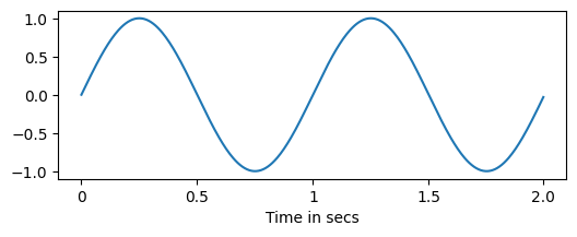
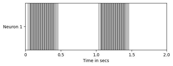
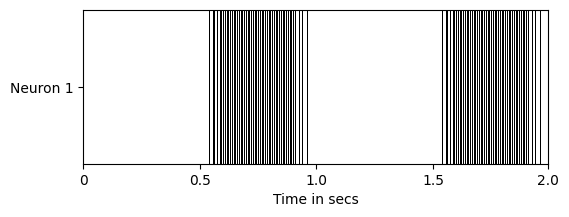
The neuron is sensitive to only the positive part of the sine wave and encodes it to spikes, however, the information from the negative part is lost. If we allow negative , and set another in the negative direction - to produce spikes for the negative part of the sine wave, then that would go against the convention of and being . It would also complicate both the neuron design and hardware implementations thereof.
One option is to pre-process the sine wave by taking its absolute value, which would ensure that the input is always non-negative (as shown in Fig. x)
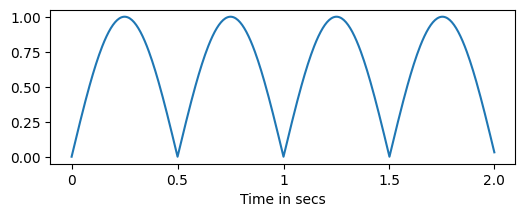
Let’s call this signal and encode it with a single neuron (again with ), as done for . Then, the following spike train would be produced (Fig. 2b)
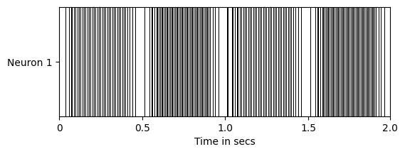
It can be easily inferred from the above that if another signal with the same wave-form as the original signal is encoded, then it would produce the same spike train as for in Fig. 2b. Note that pre-processing by taking its absolute value will have no effect as is already non-negative. Thus, there would be no difference between the spike trains obtained from the original sine wave and another non-negative signal (after applying the same pre-processing step, i.e., absolute value operation).
Therefore, let us use another encoding neuron with to encode the original sine wave ; analogous to the case of , this would encode only the negative part of the sine wave, as can be seen in the Figs. 3a & 3b below:
Thus, if two neurons - one with and another with are used, then both the positive and the negative parts of the sine wave would be encoded faithfully, and no information would be lost, as shown in Fig. 4:
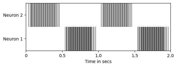
It is also noteworthy that if the signal (of the same waveform as ) is encoded via such a system of two neurons, then the neuron with would not spike at all, while the neuron with would spike and produce the spike train seen in Fig. 2b, thereby differentiating between the inputs and .
Cite this chapter
Gaurav, Ramashish; Pedersen, Jens Egholm; Bogdan, Petrut (2026). Rate Encoding. In Practical Spiking Neural Networks. Version 0.8. Open Neuromorphic. https://snnbook.net/topics/1_3_1_rate-enc
@incollection{snnbook2026-rate-enc,
  author    = {Gaurav, Ramashish and Pedersen, Jens Egholm and Bogdan, Petrut},
  title     = {{Rate Encoding}},
  booktitle = {{Practical Spiking Neural Networks}},
  publisher = {Open Neuromorphic},
  year      = {2026},
  edition   = {Version 0.8},
  url       = {https://snnbook.net/topics/1_3_1_rate-enc},
}- Eliasmith, C., & Anderson, C. H. (2003). Neural engineering: Computation, representation, and dynamics in neurobiological systems. MIT press.
- Stewart, T. C. (2012). A technical overview of the neural engineering framework. University of Waterloo, 110.